Electric scooter repair
08 March 2020
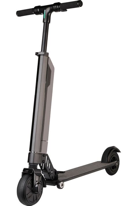
The model is a MPman TR100, supposed to reach a top speed of 15km/h (or 18km/h, or 25km/h depending on which reseller you trust), with a 250W motor and a 10s2p LiFePO4 (36V nominal, 4400mAh, 158Wh). Nothing spectacular, but I was mostly interested in having a look at its internals, and see what could be tuned, how much its power output could be improved and with what impacts on range, motor temperature, etc.
Controller replacement
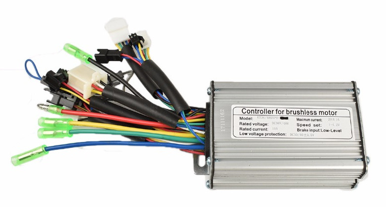
After some disassembly, it became clear that talking to the microcontroller and possibly flashing a new firmware was not going to be worth the effort. The controller box is completely filled with a gray goo, making a non-destructive extraction of the circuits very tedious.
I turned to one of the reference communities for electric vehicles, the endless-sphere forums to look for controller replacement options. Quickly the open source firmware developed by casainho, then stancecoke, then several others, which runs on easy to obtain cheap chinese controllers, drew my attention. This hardware/firmware combination allows efficient control of the motor using an simplified FOC (field oriented control) approach using sine-waves instead of simple pulses. You can configure battery voltage and current limits, speed monitoring by inputting the motor gear ratio and wheel diameter, motor power limit, etc. It can also output information to an LCD screen or an android app via a serial-to-bluetooth module, and do regenerative breaking, among other features.
As usual when it comes to active community projects, documentation can be scarce and sometimes outdated, so it’s best to head directly to the the main english discussion on endless-sphere, which is 150 pages long at the time of writing. In these cases I usually start from the most recent posts and read my way back in time until I feel like I have a good grasp of the current state of the project. It took a few attempts to find the correct motor and hall effect sensor wiring (the figure below helped a lot).
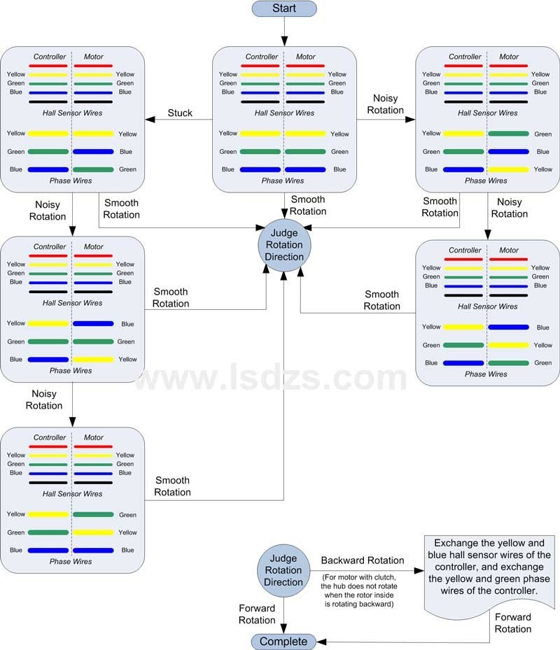
In my case I had to connect the wires (both the hall sensors and the motor coils) like so
| controller | motor |
|---|---|
| green | green |
| yellow | blue |
| blue | yellow |
After some flashing and configuring, it felt pretty great to see the motor run.
Cell Harvesting
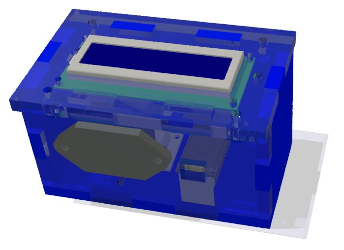
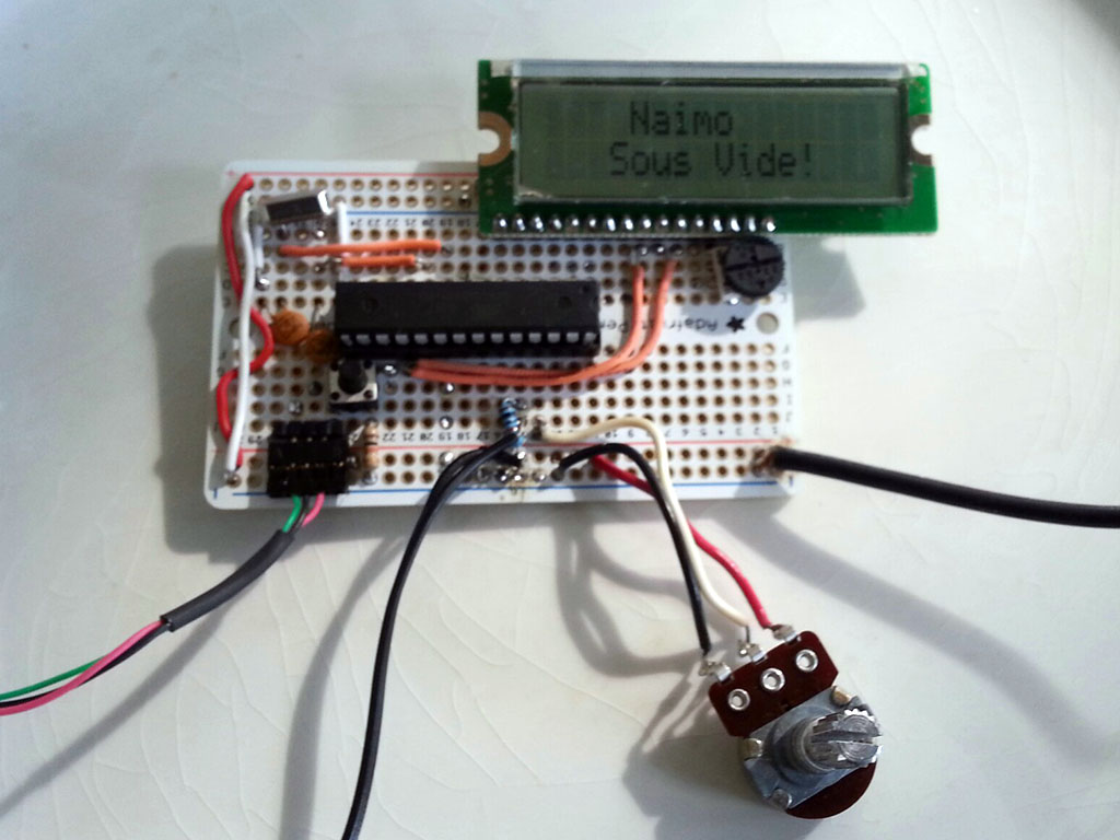
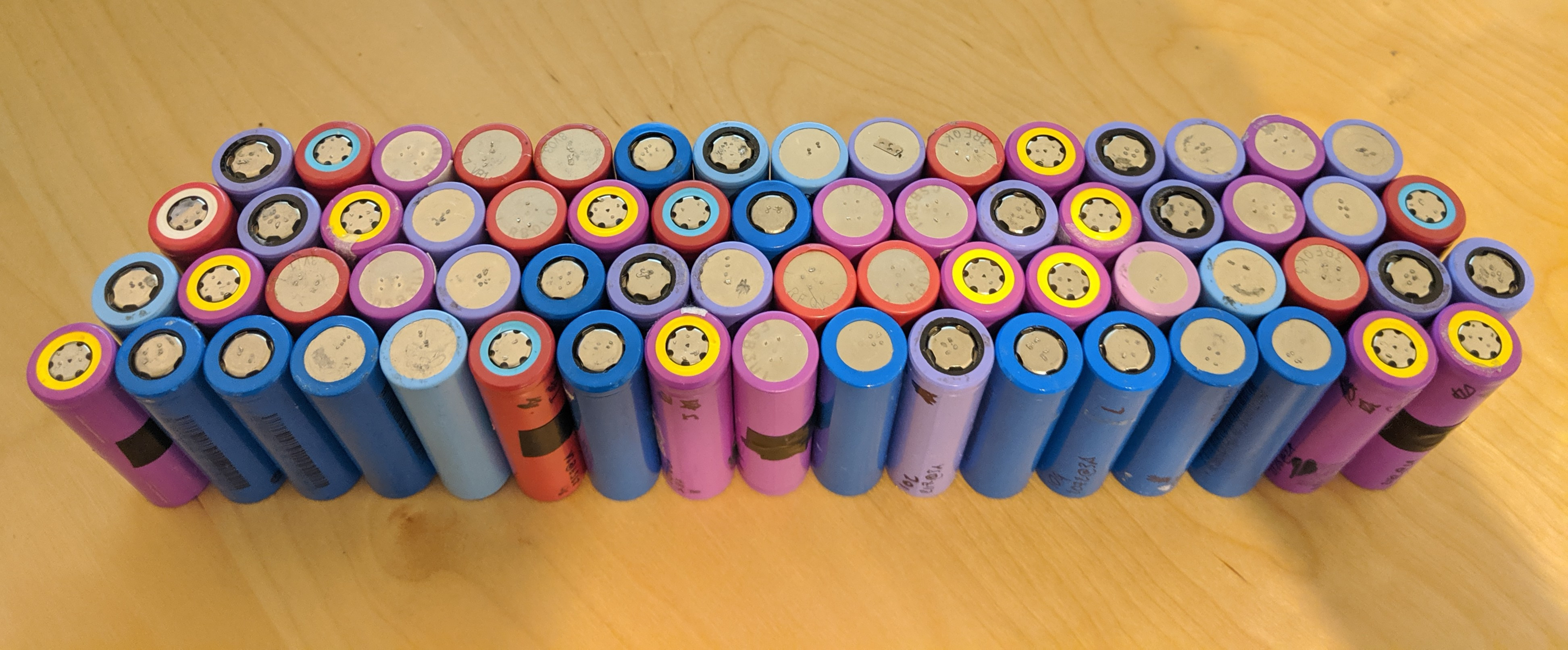
I harvested, cleaned up and tested north of 120 18650 cells using a DIY cell tester based on a basic opamp and mosfet constant current sink, a power resistor as load and an Arduino Nano. The code is available on github, the arduino outputs measurements curresponding to the cell voltage and current to the serial interface and one has to log and post-process the results separately. Beyond measuring the capacity in mAh, the discharge curves allowed me to get an approximate measurement of the internal resistance by looking at the initial voltage drop when first applying the load.
The results for different cell brands and models are all stored in a google sheet. Although name brands and higher end cells do perform better, it mostly comes down to where the cells were extracted from and what kind of abuse they received in their previous life.
Battery
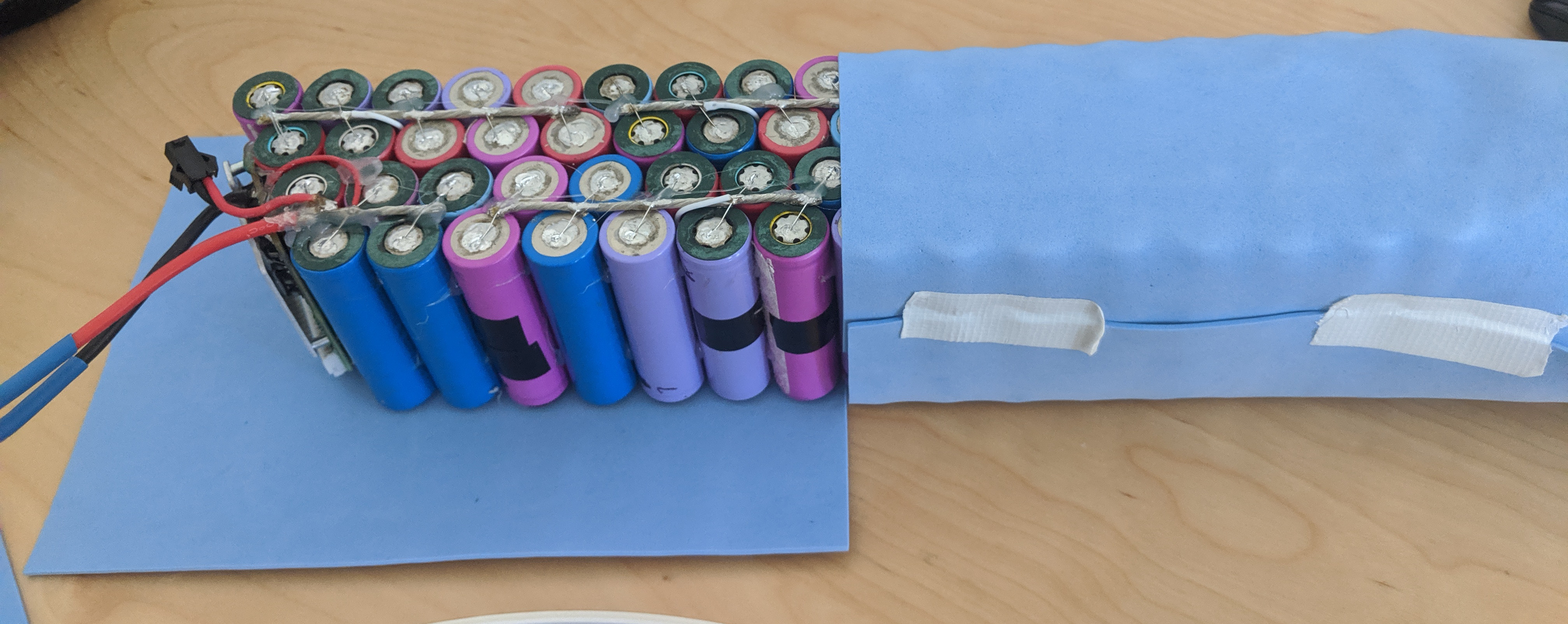
I built a 13s5p battery pack from the recycled 18650 cells, for a nominal voltage of ~48V. Their capacities tested all a little higher than 2000mAh at 3A, so the battery capacity should be right around 500Wh. After assembling the cells in the right arrangement with hot glue, I soldered them with thin copper wire (leads from through-hole resistors) for the parallel connections, which act as fuses and fail above ~8A, and thick wire (16AWG multi-strand) to connect them in series. I believe that this “cell-level fuse” assembly method, often used in the diy powerwall community, was introduced by Tesla. It protects the whole pack form a single cell failure.
Although there was a risk that the heat from the soldering iron might damage the cells and decrease their capacity, the alternative was to use a spot welder which I couldn’t justify acquiring (yet ^^). Because the cells from laptop batteries are not rated for a high continuous discharge current, and since I only tested them at 3A, I will be limiting the current of the whole pack to ~12A. This should compensate the differences in internal resistances which will lead to an uneven distribution of the discharge current among the cells in a parallel group. Despite this low current, I should still get an improvement in performance and significant increase in capacity compared to the stock battery.
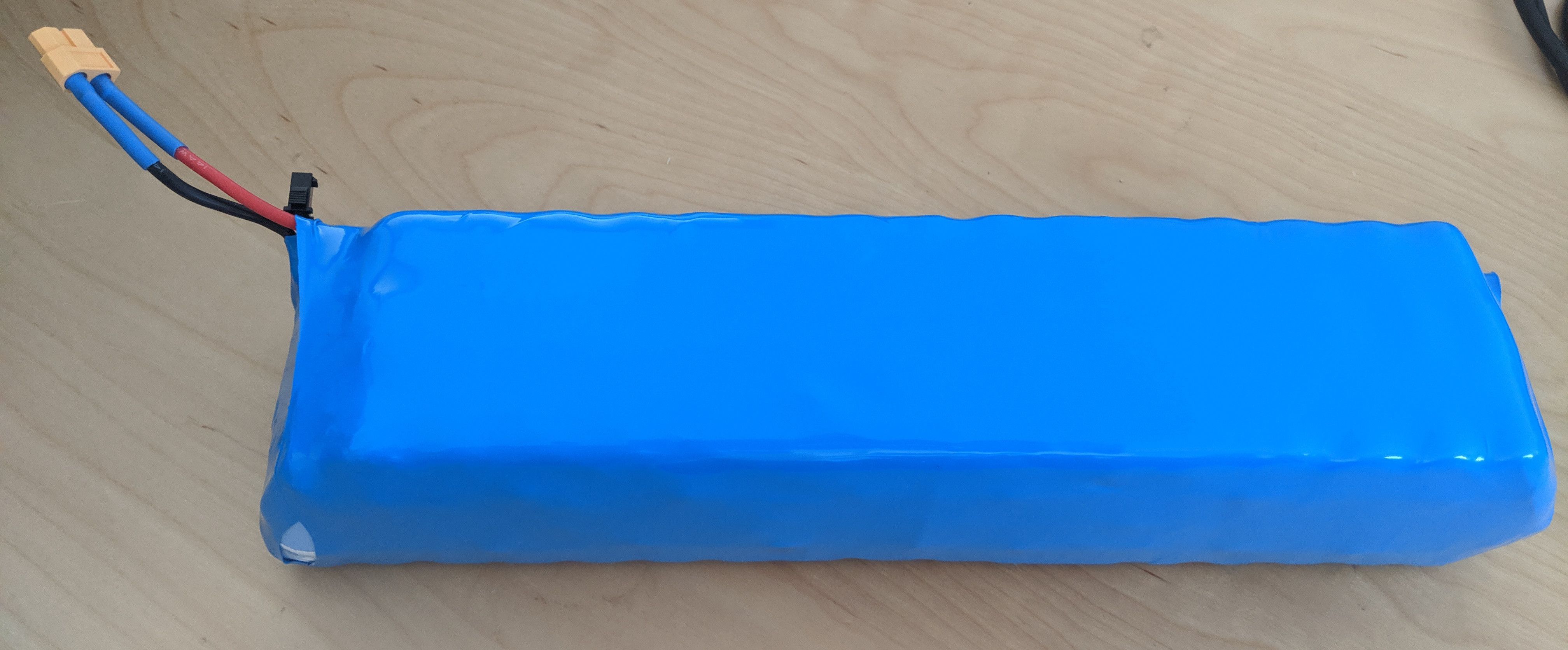
I then added the BMS (battery management system), which monitors the voltages of each of the 13 groups of 5 cells and cuts the power if they deviate too much from each other, among other things (it also does over-discharge, over-charge protections, etc.). Once the soldering was done, I protected the pack with waterproof foam and shrink wrap.
Assembly
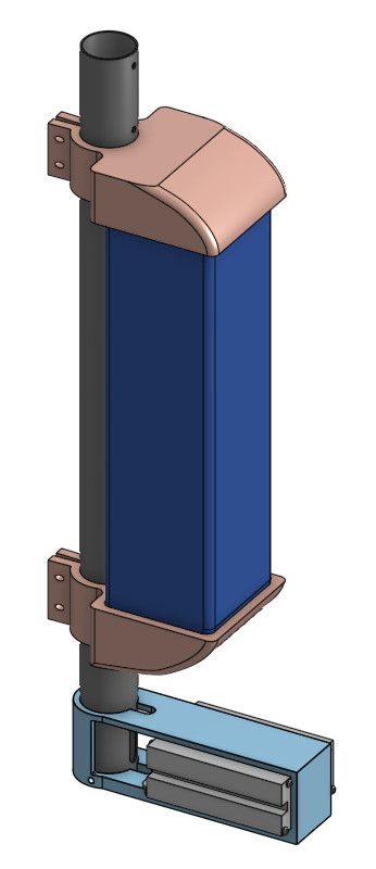
After some early tests with zipties and elastic bands and tape, the looks on bystander's faces (and more importantly the constant shifting of the components) convinced my that I had to come up with a somewhat more finished product. So I printed some parts to hold the controller and battery and printed them in PLA. It still definitely looks home-made, but at least things are secure and at a low risk of falling off in the streets.
What's left is to print and mount some fenders (one of them probably acting as an emergency rear brake when regenerative braking is not enough) and lights.
Results
With the new battery and controller, I am pretty happy with the performance of the scooter, I can easily reach 25km/h and have a much easier time going up slopes. Placing a power meter between the battery and controller, I could verify that the current limiting feature of the controller works and I get peak currents just above 12A and powers up to 650W. That’s electrical power, so with the losses in the controller I hope I’m not pushing the motor too much. It gets quite warm at the end of a ride but not too hot to touch, I’ll definitely keep monitoring that.
The longest ride I’ve done was 12.4km and consumed 6.08Ah or 252Wh, bringing the energy consumption to right around 20Wh/km, at an average speed of 20km/h. Assuming I can use the whole 10Ah of my custom battery, I should get a range right around 20km. It’s not very efficient when compared to the 30km real-world range at full speed of the M365 pro which has 480Wh of battery. I attribute the lower efficiency partly to the smaller wheel, but there are perhaps still some improvements to be done on the firmware side (phase of the pseudo-FOC, waveform…). One day maybe..
Other projects